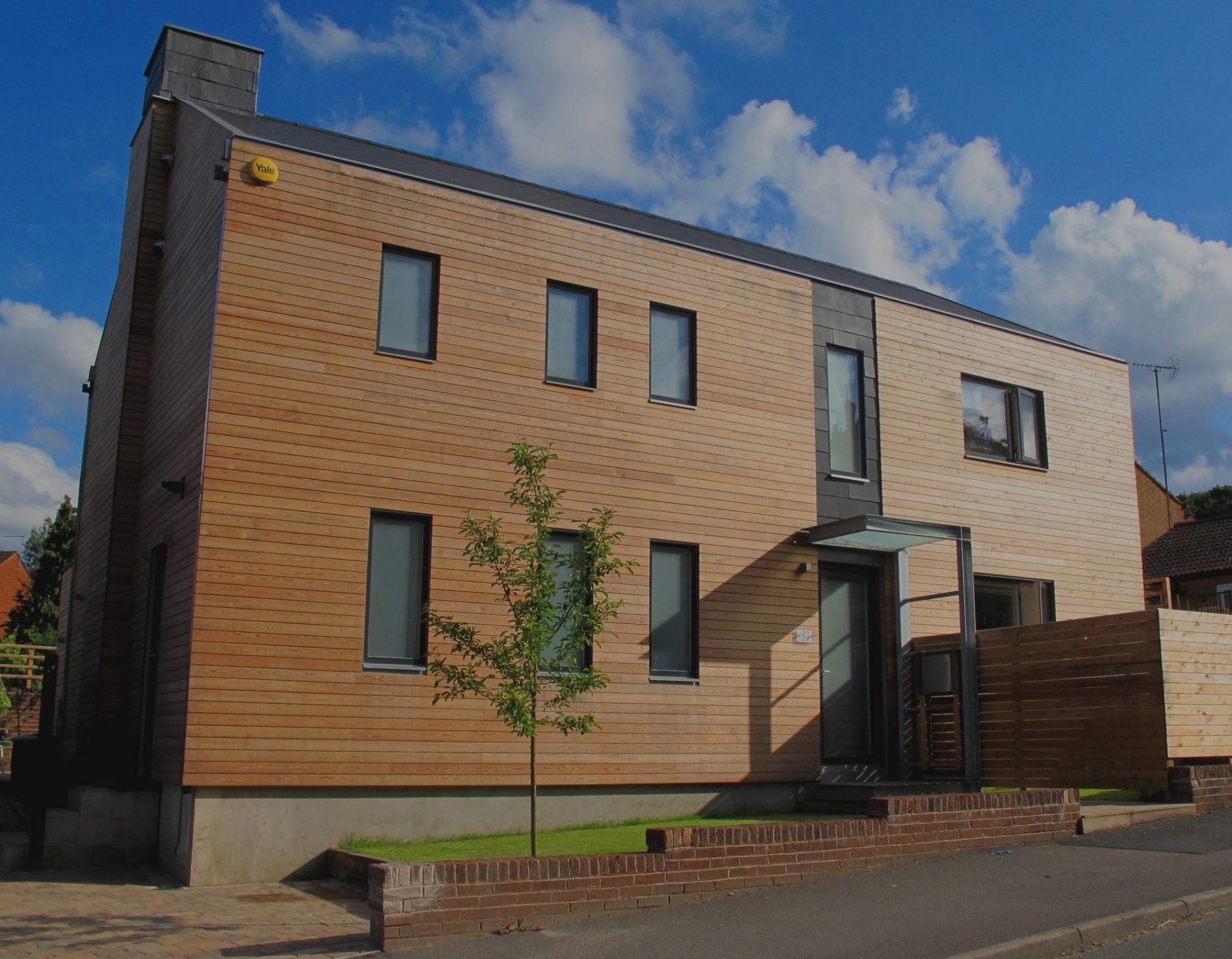
This page documents the transformation of a 1950’s detached property from a banal, cold and draughty house into a fully certified Enerphit whilst improving the design internally and externally.
I hope the following photo’s and descriptions will be of help to anyone thinking of undertaking a similar project.
Link to BBC Look North Article –https://www.bbc.co.uk/news/av/uk-england-south-yorkshire-54119162
Overview
The property is well suited to Enerphit for the following reasons
a) Living accommodation with a reasonably southerly aspect
b) Detached so relatively easy to insulate externally
c) Raft foundation and higher than normal ceiling. This provided an airtight floor structure with space to insulate over.
d) Internal drainage – the external insulation did not effect drain positions.
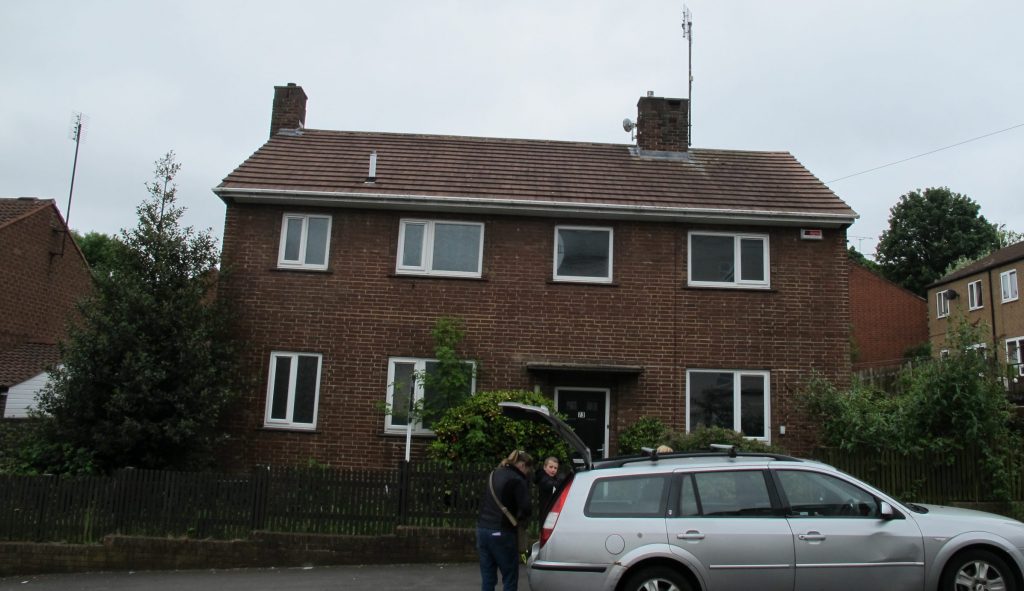
The property before renovation, brick construction throughout built of a raft foundation wtih a concrete tiled roof with purlins and rafters. After a house warming party the messy work began.
The project was undertaken as a stepped retrofit, i.e. where existing window openings remained the same size the windows were reused for a period (construction phase and for a few months of occupation). This was to stagger the cost of the triple glazed composite windows.
Demolitions
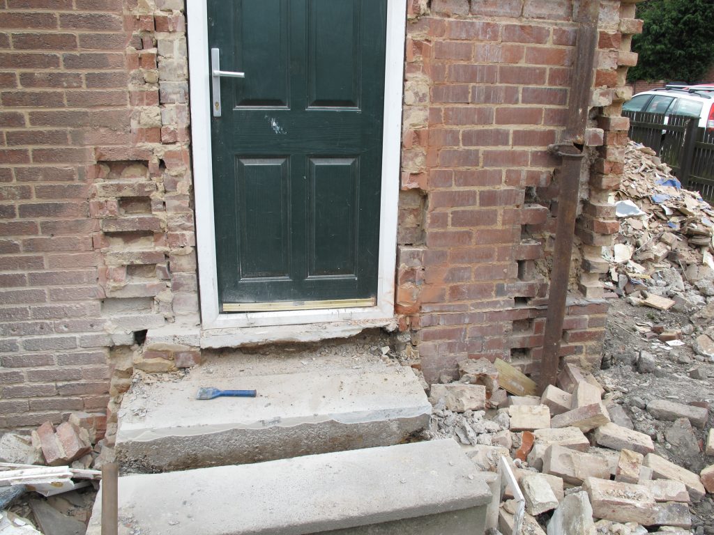
Basically all unecerssary protrusions were removed, the central chimney, projecting concrete canopy, coal house, steps and external abutting walls were demolished and made good (the harder part), walls pointed as required.
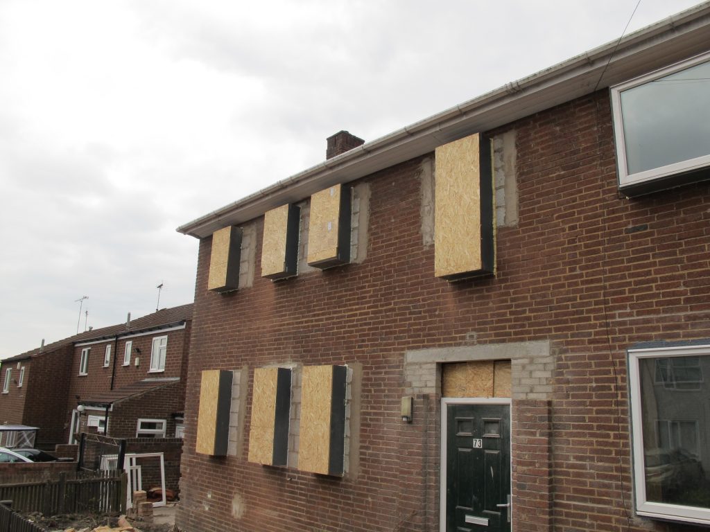
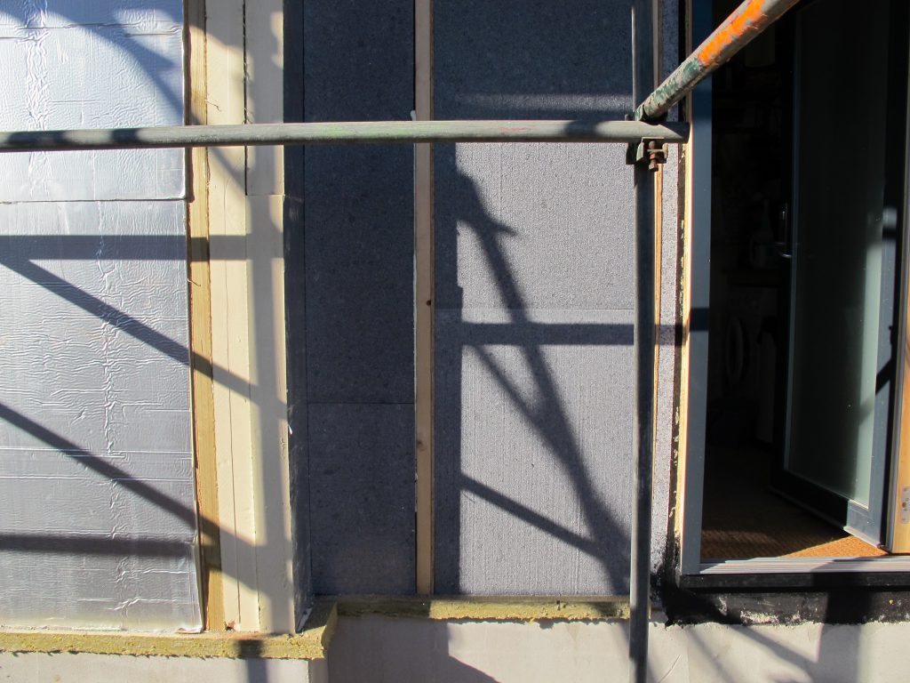
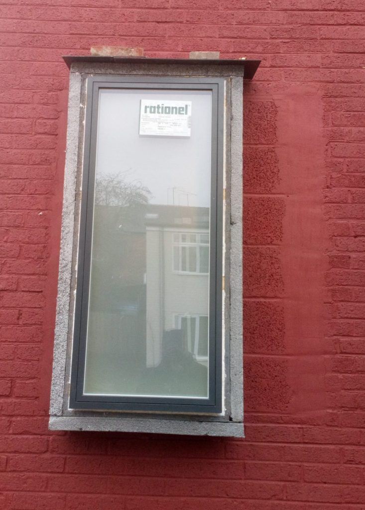
Windows to the north side were rationalised and reduced in size slightly and OSB3 boxes installed to push the windows out into the external insulation zone. Note the OSB was protected with liquid applied waterproofing, intended for roofs. At this stage I was still considering using the external face of brickwork as the ar tight line. In hindsight I would wait until later to install the window boxes, as although they were weather proofed I didn’t expect full summer/autumn/winter exposure.
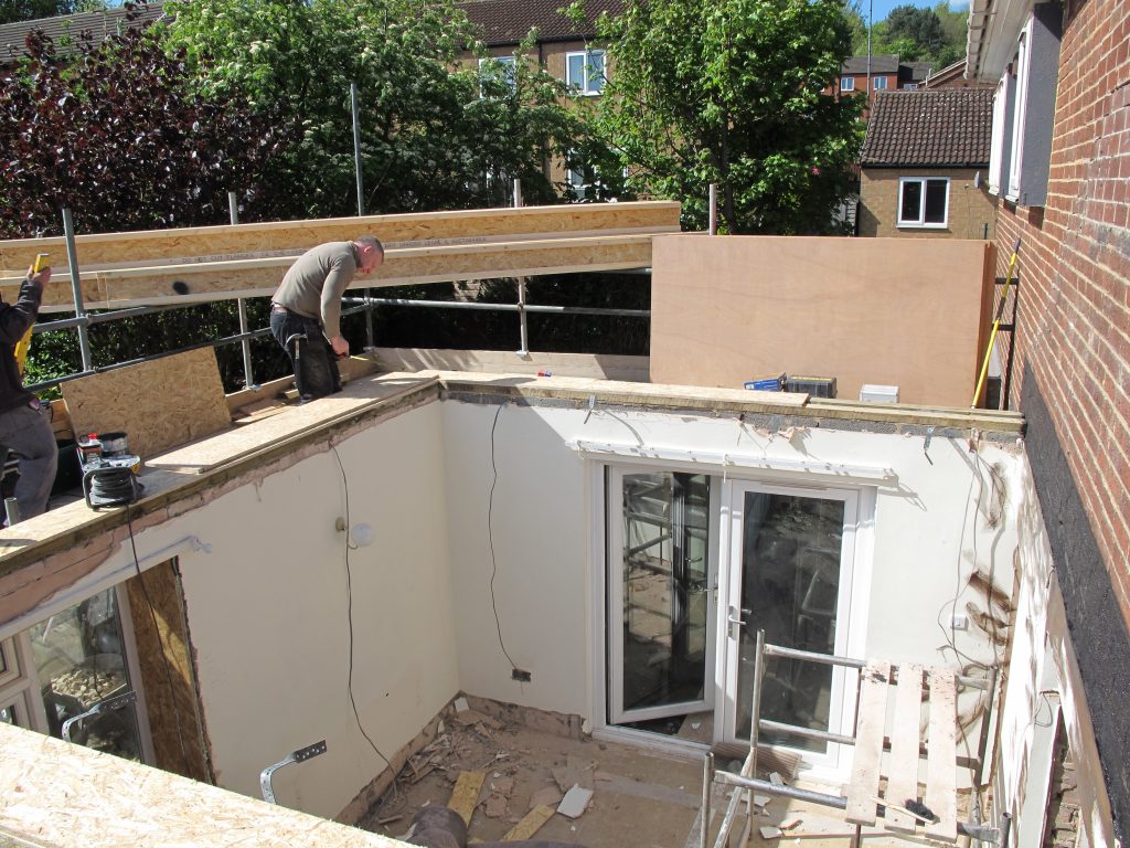
The pitched roof of the dining room was removed mainly to allow the inclusion of a south facing window at first floor level. This revealed that there was originally a window in this position before the extension was built in the 80’s.
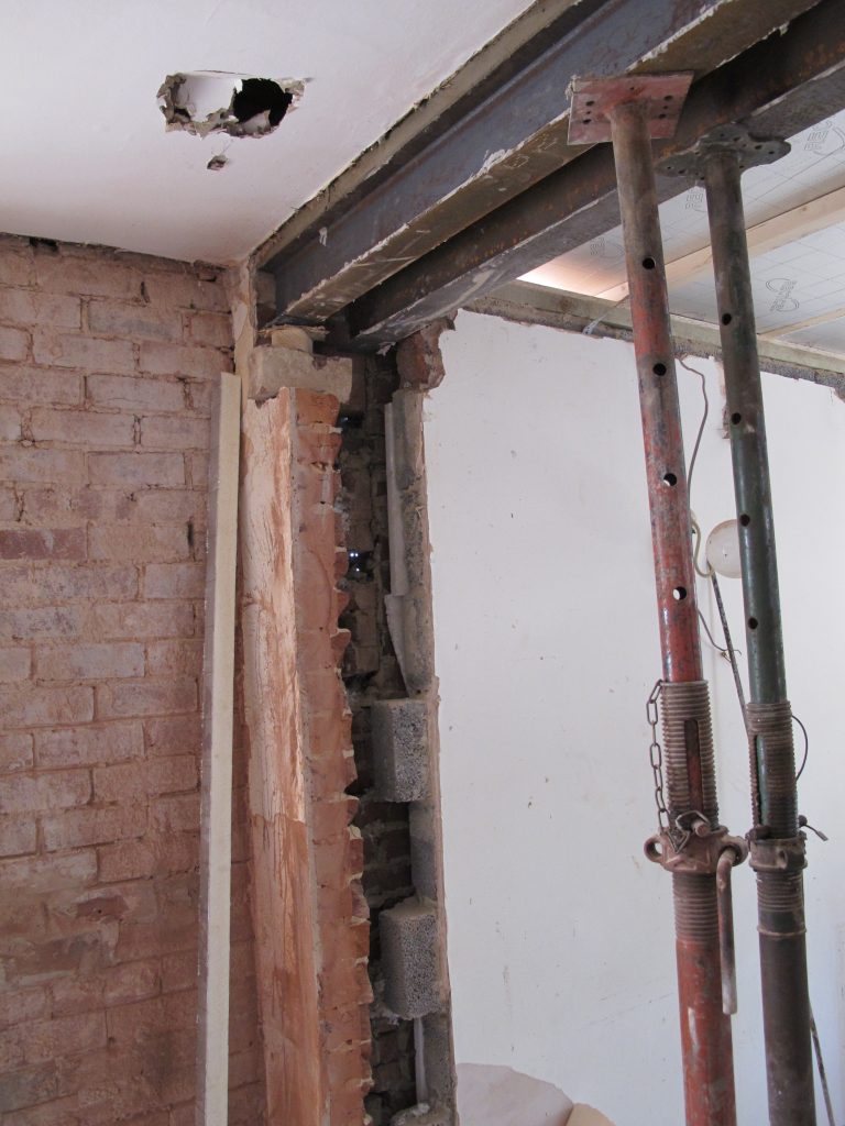
The only new steelwork was to support the enlarged opening between the kitchen and dining room
Roof
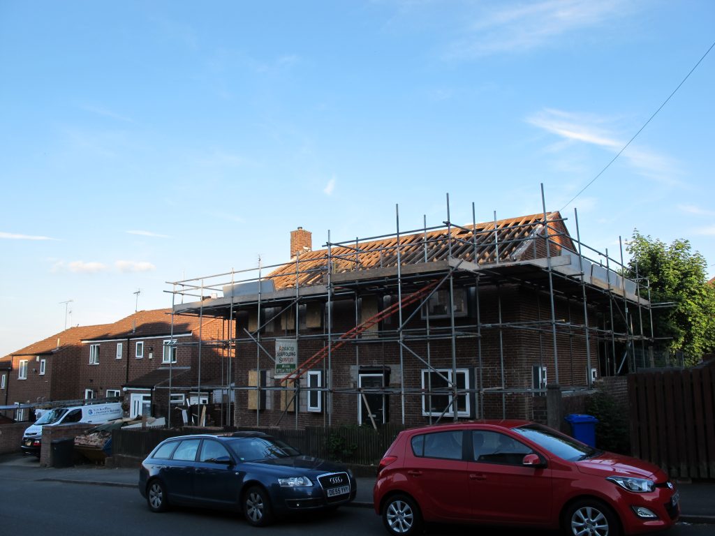
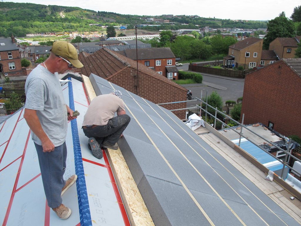
After installing the window ‘boxes and refitting exisitng windows scaffold was erected and the roof stripped. This was one of the more stressful points of the build even though the inside of the house was only a basic brick shell. Luckily the weather was kind for the next few weeks.
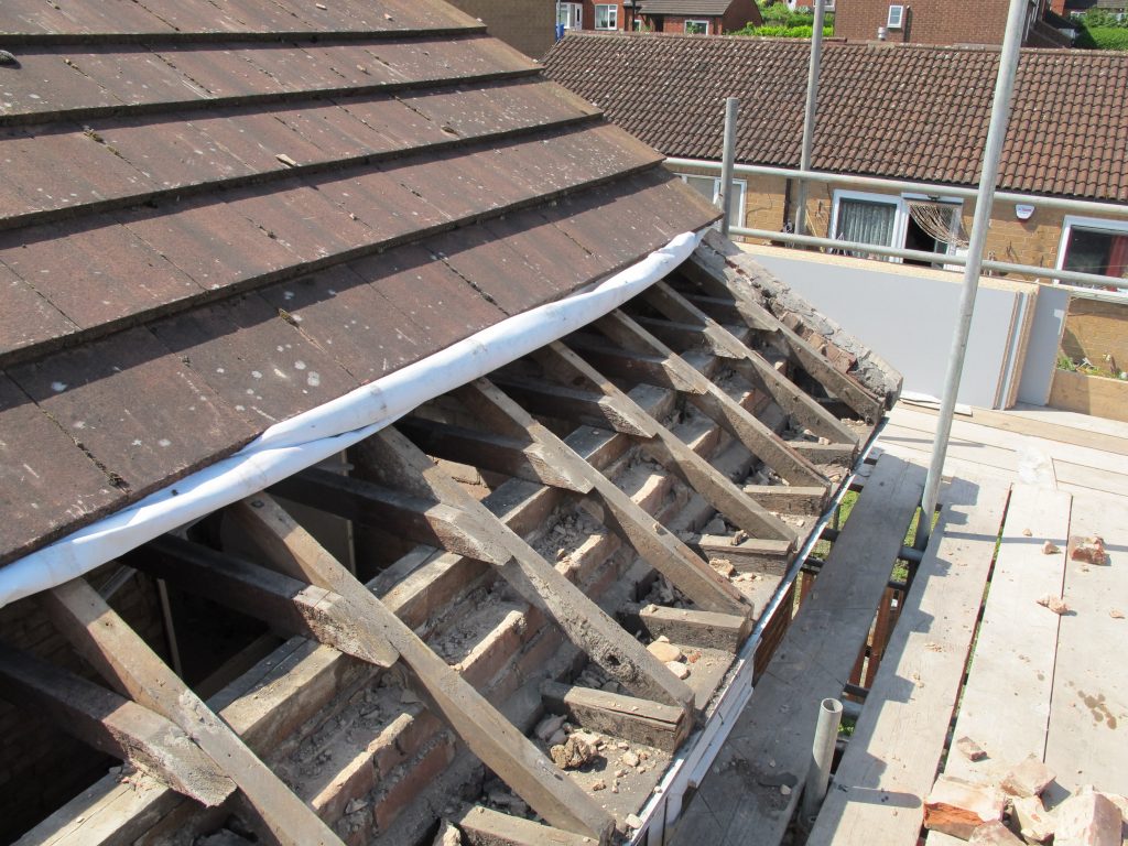
Rather than striping the roof and then dealing with the remodelling to enable the new roof and associated airtightness detail, we first removed the eaves tiles to reveal the structure. This was one of the areas where asbestos was present, asbestos cement soffit – hidden under UPVC cladding. The roofing felt was retained and it made it possible to keep the roof watertight between various stages of the eaves works.
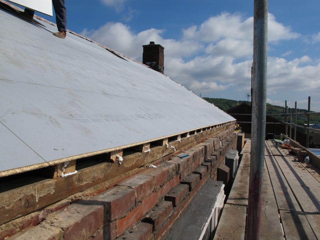
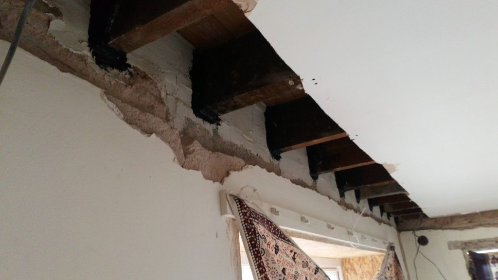
The critical design change to the roof was the change to a warm roof, i.e the insulation on the outside, freeing up the loft space as usable space within the thermal envelope. This meant the air tightline now followed the top of the rafters. Here the weather resistant flooring chipboard was used as a deck which formed the air tight line, the internal finish and substrate for the roofing over. These boards had a rough surface providing a relatively safe working platform. The pockets from the eaves construction were filled and then the brickwork rendered to improve air tightness and generally consolidate the masonry providing a surface which would accept an airtight tape or paint connection.
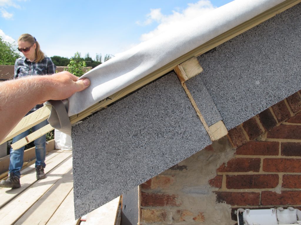
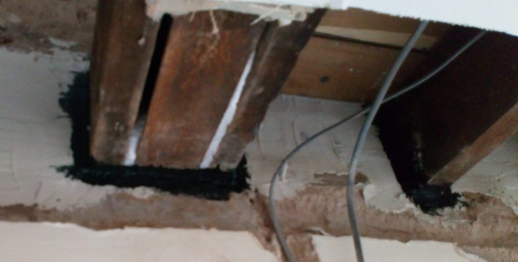
The main deck was t&g jointed glued with foaming PU glue and then the joints taped externally, with sheathing board jointing tape. The cut joint capping the joist ends and wall plate was sealed with proprietary air tightness tape (Pro-clima) The junction between the board and the masonry was completed with liquid applied air tight membrane (blower proof). The membrane visible in this shot was temporary weather protection to the eaves details (taped to the deck)
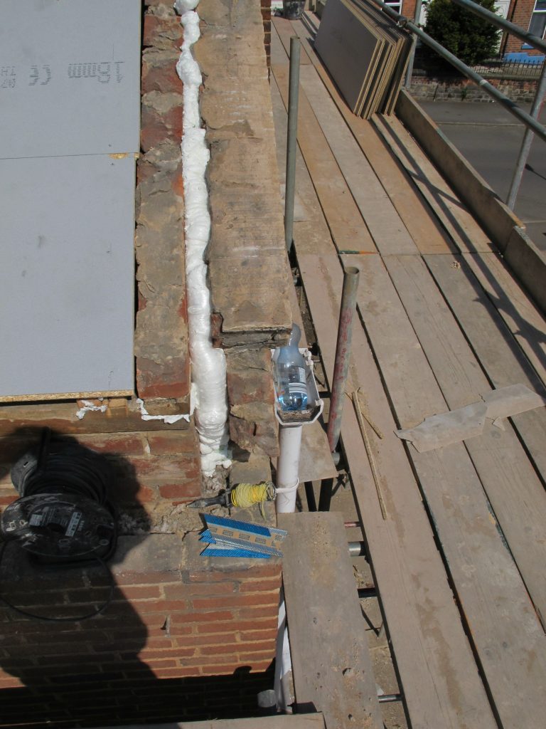
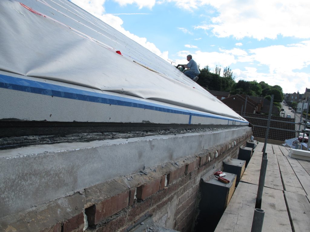
Airtightness at the gable junction involved crude use of air tightness foam to ‘cap’ the wall cavity. Here it is difficult to complete air tightness internally due to rafters being close to the external wall surfaces and the simplest way of connecting the deck to the walls was externally
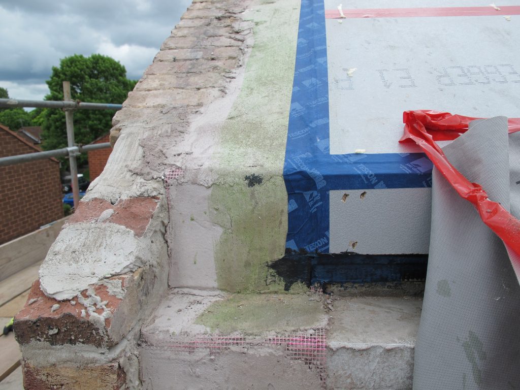
The head of the gable wall was then rendered and primed before linking the deck to the wall with proprietary air tightness tape. Note these tapes are amazingly sticky, but primers are required on substrates such a render/concrete, here the primer shows as green.
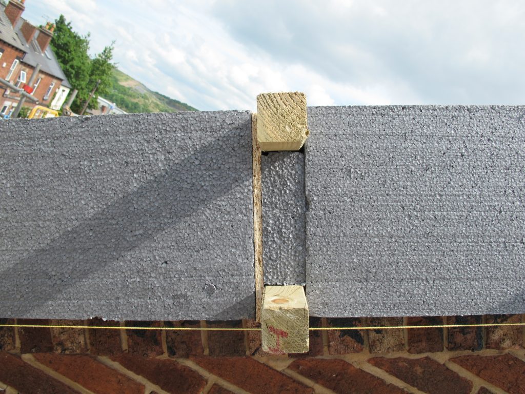
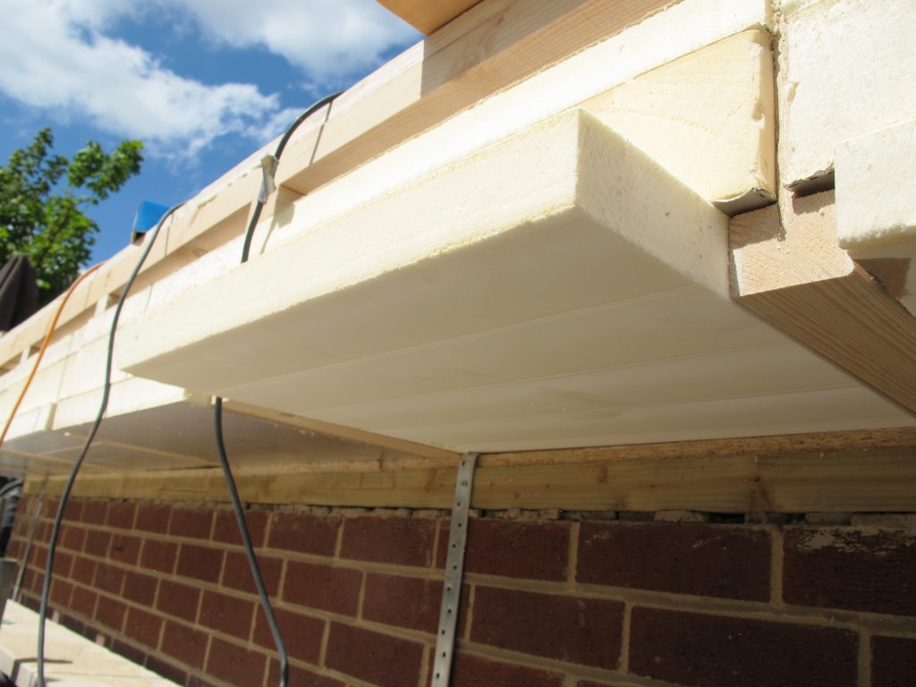
Now the deck was sealed to the walls installation of 240mm of graphite EPS + 50mm mineral fibre insulation could begin. The main problem with thick insulations is fixing through it, especially when the rafters below are only 50x75mm. Specialist fixings do exist for thick insulations but the specialist software rejected fixing into such small timbers. So instead we fabricated OSB webbed beams to fix to the existing joists, 45x45mm battens fixed to the existing rafters, 9mm OSB3 linking to a 45x45mm top batten to which the new roofing battens were fixed. These were laid sequencely with the 600x1200mm EPS insulation boards to ensure a tight fit and reducing the need to cut the insulation boards.
The prefabricated roof rails cantilevered over the gable ends ready for the external wall cladding to abut.
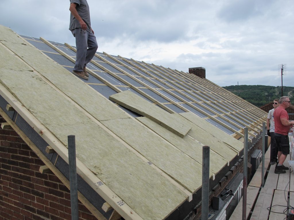
The roof and walls were all encapsulated in mineral fibre to create a fire proof protection layer to the EPS as such a thick layer of EPS made me nervous even though it wouldn’t be required by building regulations. Here 50x75mm C16 timbers were used as these provided the eaves cantilever and fixing point for the new gutters. Again these were set out by the size of the insulation slabs.
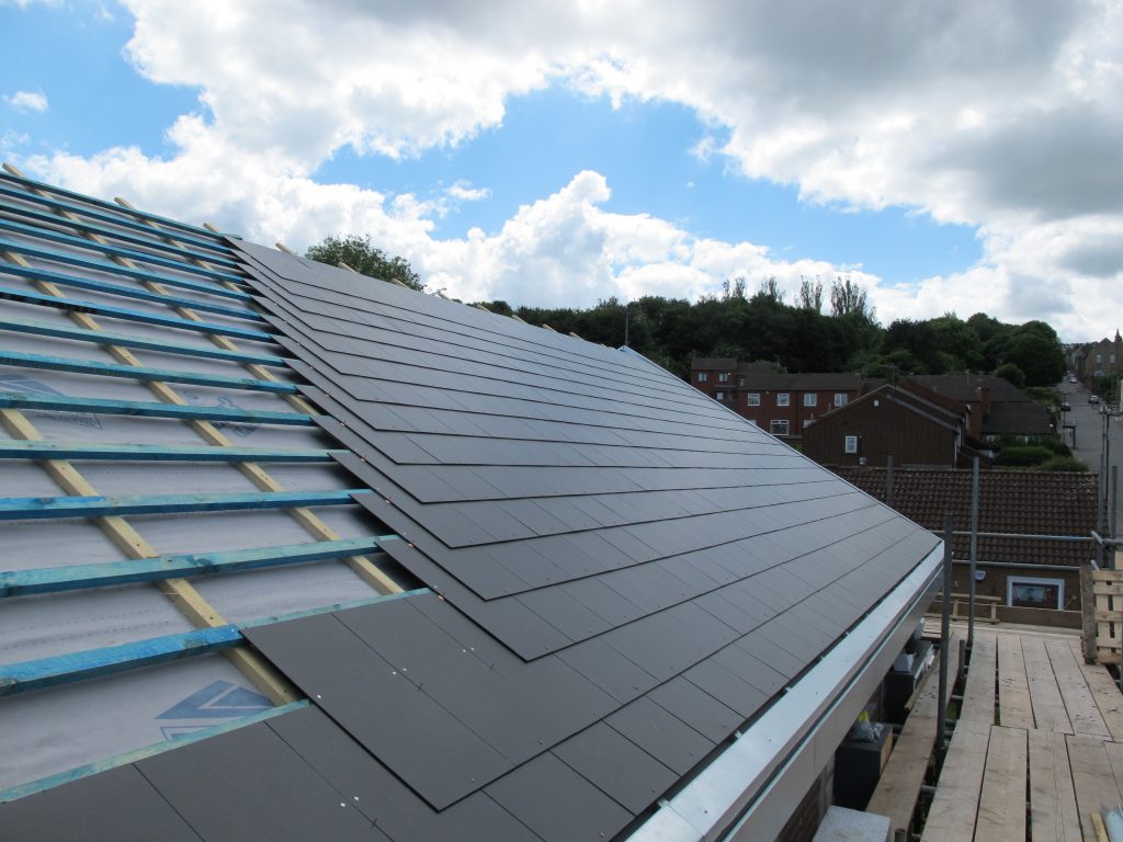
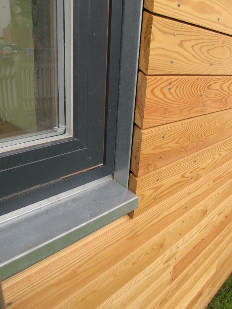
Fibre cement slates were used to finish the roof as these were the lightest option as building control wouldn’t accept additional loads on the roof, unless proven by a structural engineer, who couldn’t prove it could! The gutter is a bespoke membrane (EDPM) lined galvanised sheet steel designed to be concealed behind the timber cladding, to be installed later.
Dining room roof
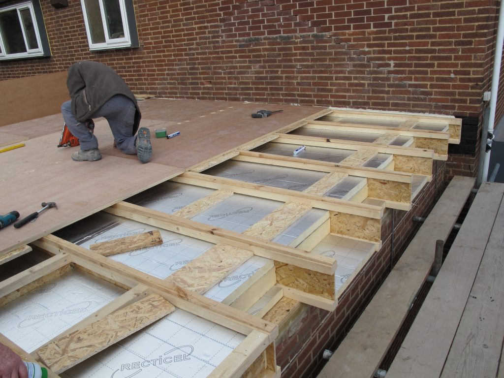
The new dining room roof was design as a ventilated ‘cold’ roof to save on build up depth. This was also the reason for using PIR insulation. The joists were 245mm deep, so with 200mm PIR 45mm remained clear for ventilation, with an extra 10mm created by the firrings. The PIR was tightly fitted between the composite joists so the insulation was only bridged by 9mm OSB.
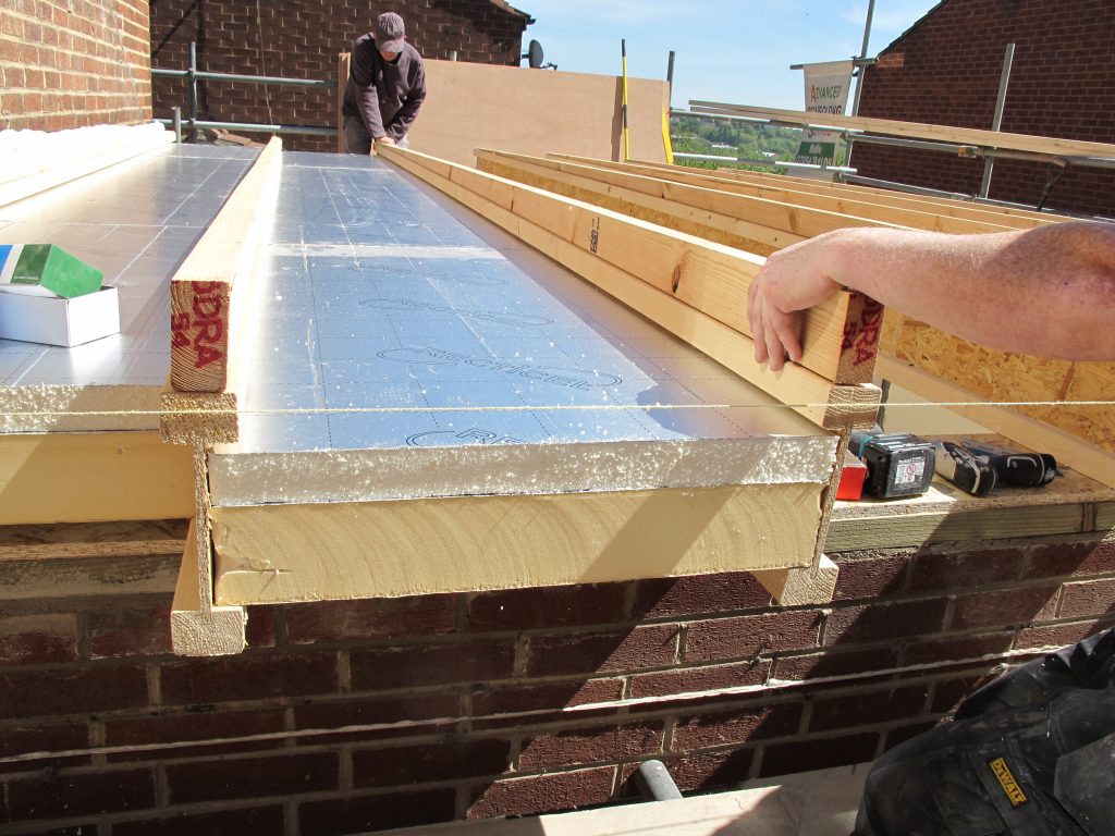
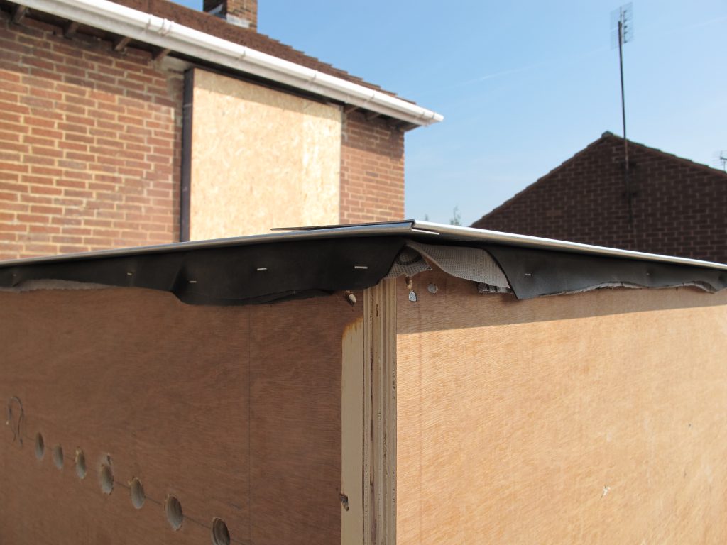
The roof again had to cantilever over the existing walls ready for the external insulation to be fitted later.
I was unable to find any information on the effects of foil facings creating cold bridges in certain locations, so to be sure it was removed were insulation spanned from cold to warm, such as the roof perimeter.
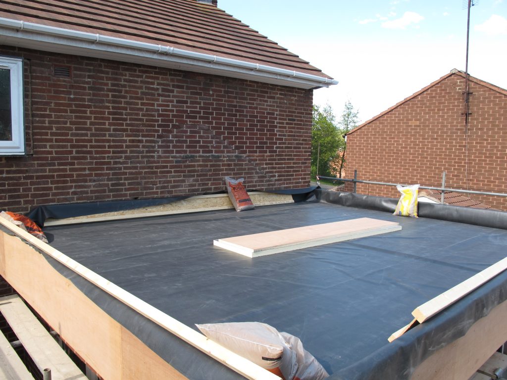
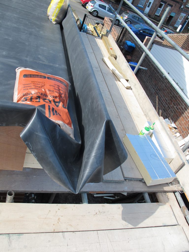
The roof was water proofed with a single sheet of EDPM, loose laid with pig ear corners, so no jointing or adhesives were required.
Internals
Once the roof was completed we needed to concentrate on the internals to get it livable again, it was pretty much a brick shell at this point. Prior to plastering air tightness working needed to be carried out, as by this point it was decided that the air tight line was to be the internal plaster. The original idea of using the external brickwork face was abandoned due to the construction of the existing dining room extension, as unlike the main house it wasn’t built off a raft. Instead it was built of deep strip footing which must have gone through the depth of the built ground. We never excated deep enough to find the top of the footings, and even if we had, linking the external face the internal slab would be impossible, unlike with the raft foundation, so the decision was made. This now meant air tighting joist ends and internal window box junctions etc.
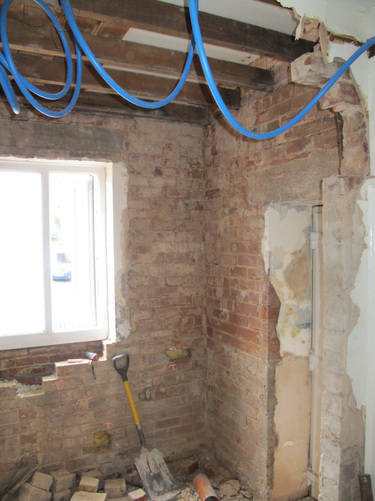
When starting to strip wall paper it become evident that the plaster was shot, and the above is what we got to.
Upon opening up the floor along external wall lines it becomes obvious why so much unwanted air leakage occurs in this area in most tradionally built houses. Whole bricks were missing in places. Brickwork was repaired and pointed, a parge coat applied to the face of brickwork within the void areas and then airtightness paint applied around joist ends. It is in these messy & fiddly locations that we found liquid applied air tightness membrane to be best.
The diffucult areas to airtight were where the joists ran parallel to the steels, and the joists parallel to external walls. Here again crude use of airtight PU foam was used (after cleaning out as much dust and debris as possible). The back up plan was to remove brickwork externally and seal from the cavity side, gladly this wasn’t required. The junction between the wall plate and brickwork was also sealed with airtightness paint after making good as required.
Windows doors
The temporary use of existing doors and windows led to a couple of complications. Reusing these meant that the structural openings created by the new projecting boxings needed to be the same size as the existing masonry openings. For the windows this entailed a stepped boxing where basically two boxings overlapped.
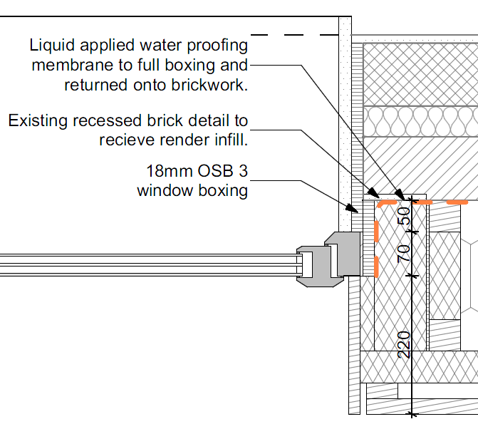
This detail didn’t work with the doors however as the original opening was reduced by the thickness of the OSB and therefore clashed with the hinges as they were inward opening. Here we linked the external boxings to the masonry using galvanised sheet steel. This reduced the internal opening size by less than 5mm so could be accommodated.
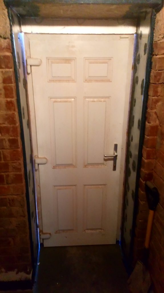
All external and internal door lintels were lifted to accommodate a floating floor on top of the existing.
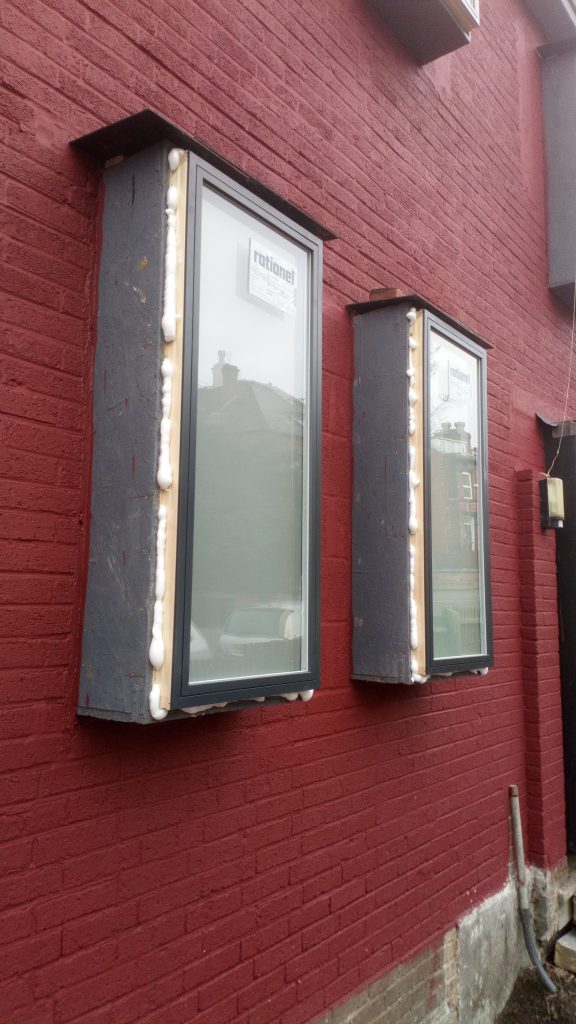
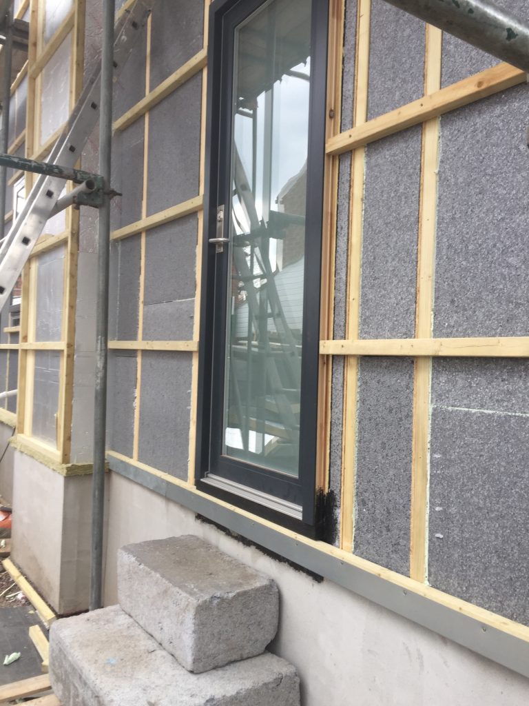
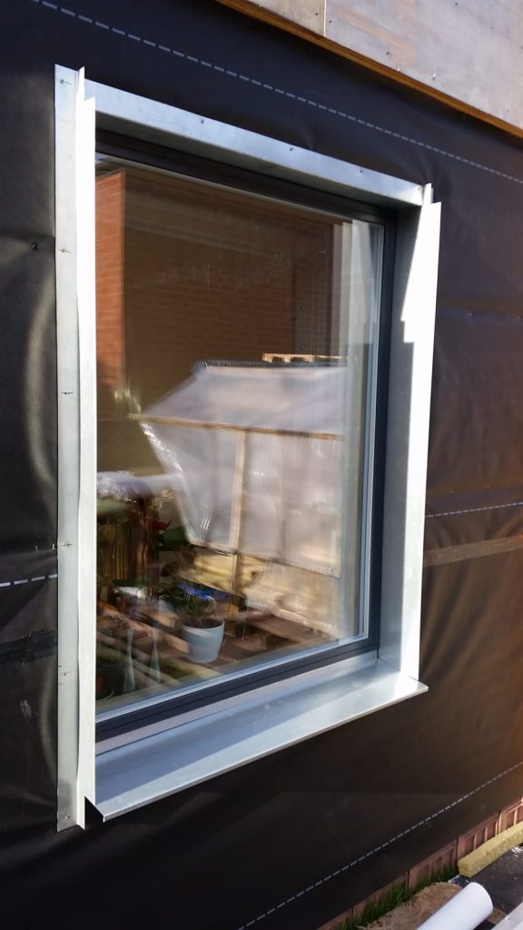
The newly formed window openings were the first to recieve new triple glazed windows (Rationell Aura Plus). These were then air sealed to the OSB boxings internally.
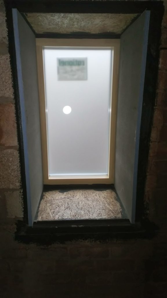
This meant that internally where first phase windows were installed they could be fully plastered. The windows which still had the existing windows in were left with exposed OSB reveals to allow for later air tighting.
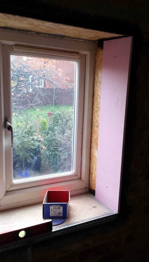
The plaster board lining stopped short of the window frame to allow the installtion of air tight tape once the new windows were installed, but projected 10-15mm beyond the internal brick face to allow the internal walls to be plastered.
It was the start of the plastering, unfortunately during the winter that exposed the problem of condensation forming heavily inside the OSB boxings. We painted them internally with whatever we had to hand as one measure, but also insulated them externally.
This solved the condesation issue, but with our terrible winter weather I was concerned over the durability of the boxings as the build was going slower than hoped, so more time and effort was put in to protect them externally. Note the roof slates forming a temporary roof over – this worked well until really heavy and windy storms hit.
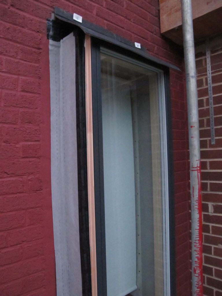
As the new windows are obviously an expensive item it seemed worth the considerable additional effort to insulate then dress in breather membrane and seal out of sequence somewhat. It would have been better to complete the cladding but didn’t have the cash or labour at the correct time.
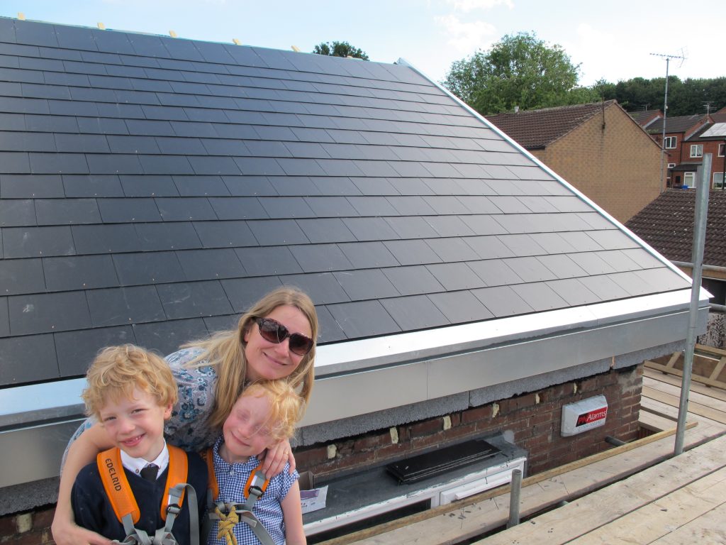
Moving in
Once the inside was habitable we moved in, although we still didn’t have staircase or a working ventilation system we had some plastered and decorated rooms, a downstair WC and used the utility area as the kitchen. Kids were fine with using a ladder, but we had to send them of to the grandparents so we could finish the bathroom.
Ventilation system
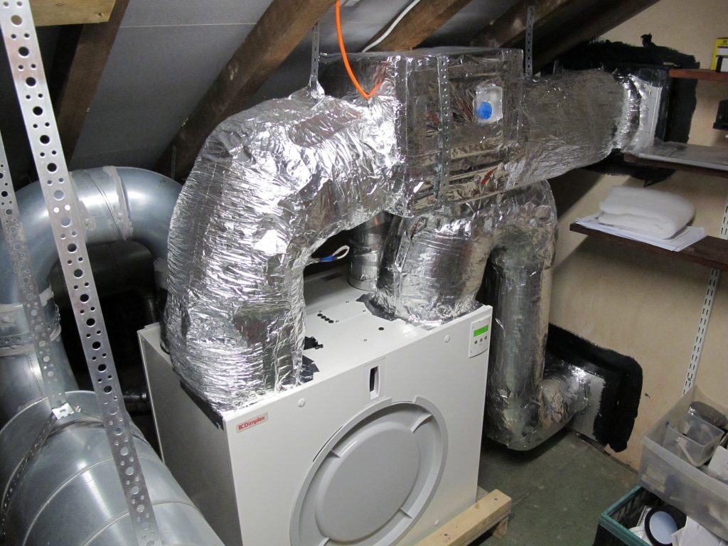
The biggest problem we had was with the ventilation system. I was a few weeks behind getting the ductwork finalised only to discover a fault with the Heat recovery ventilation unit. When I checked the heat exchanger I discovered it was faulty so had to request a replacement & unfortunately this took a couple of months, which for a piece of equipment vital to the functioning of the house is totally unacceptable. For this reason I would strongly recommend against using a Glen Dimplex/Xpelair unit as their customer service was shocking. It has also been impossible to get a full manual in English. So in this time we had internal condensation and humidity problems, from mold on walls to the Oak floor expanding and buckling up.
These problems settled down quickly after getting the unit up and running, and it has been functioning fine for over a year now.
When choosing a unit future support is crucial as is the ability to get hold of replacement filters, which seem to be excessively expensive in the UK. I have also been suprised at how quickly the external fly mesh on the external inlet can become blocked, made evident by the increased noise in the system coming from struggling fans.
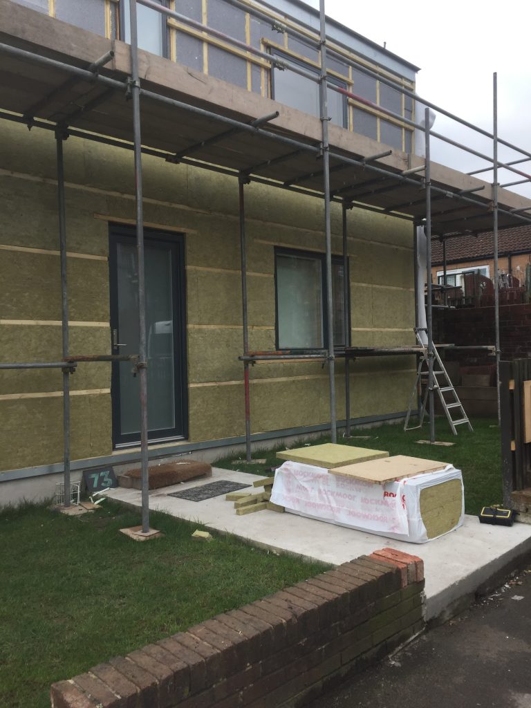
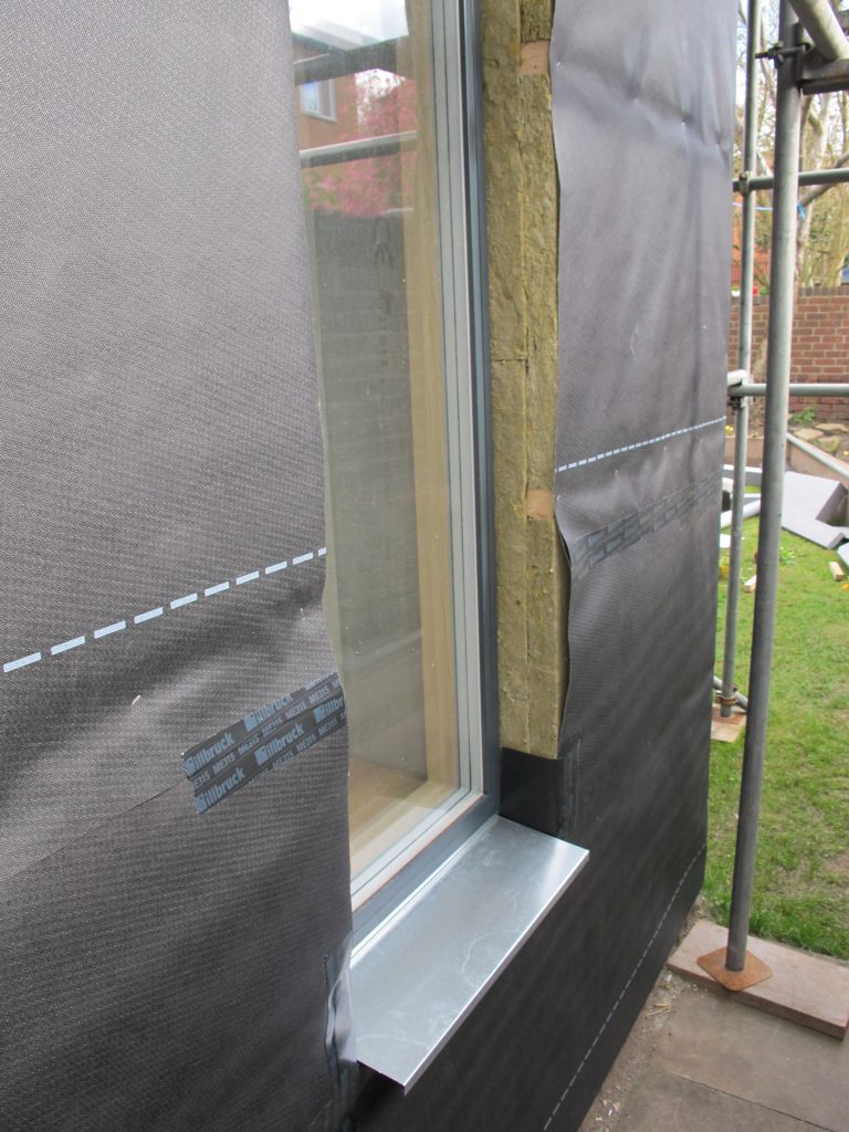
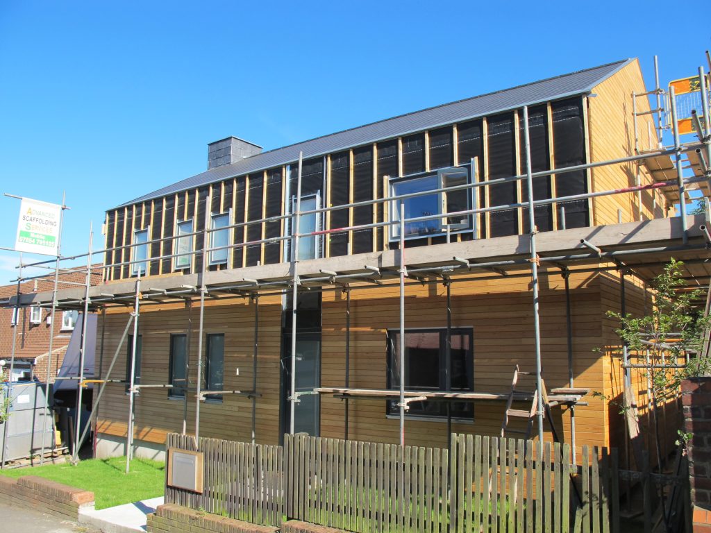
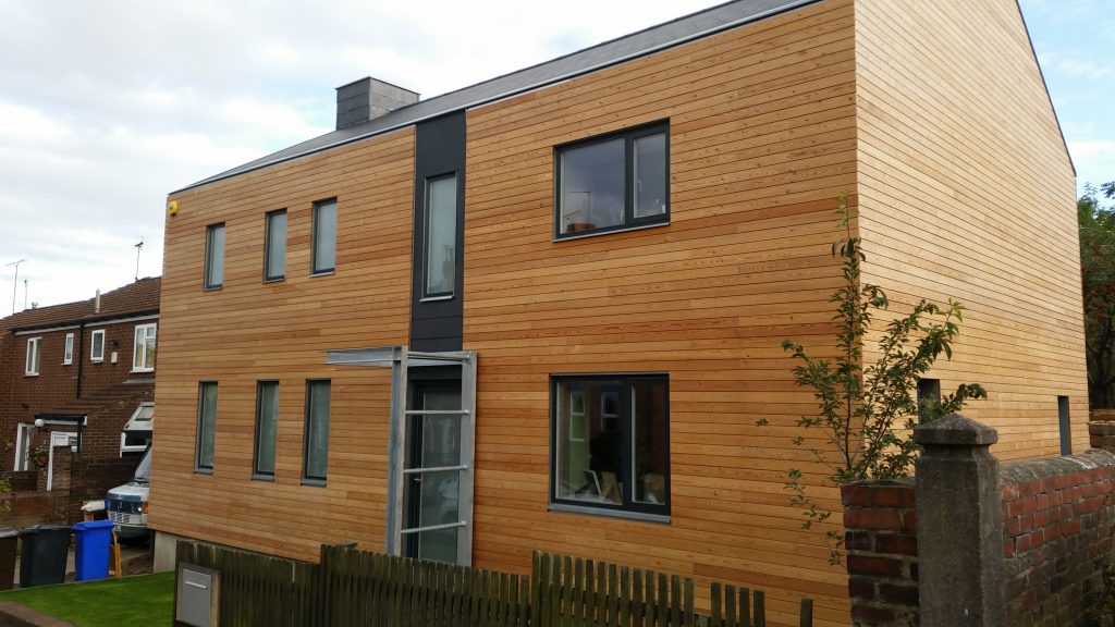
Cladding
Now the roof, windows, floors, electrics etc were complete we moved in and started the external cladding.
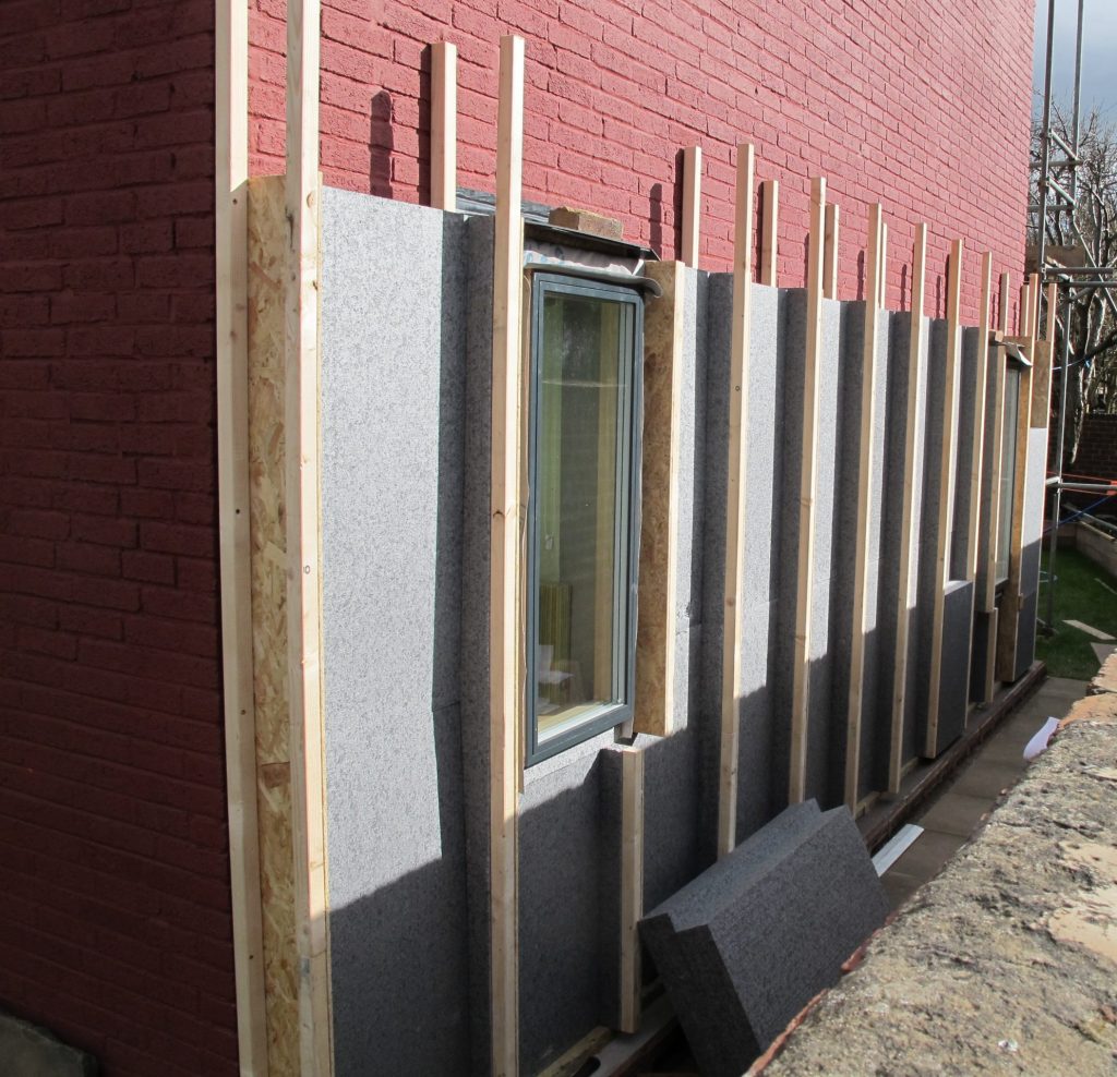
The cladding rails were again installed sequencely with the insulation boards ensuring a tight fit and minimising cutting and joints staggered.